eMotion 5075 teardown
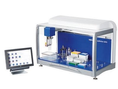 In my PhD lab we had an epMotion 5075 pipetting robot. I had a like/hate relationship with this machine. Like: it’s an impressive, precision-engineered, piece of hardware. Hate: the software is appalling. Writing protocols for it was slow, frustrating and generally awful, and there was a general lack of flexibility in what one could make it do.
Recently I heard that the lab was having a clear out, including disposing of this (pricey when purchased) robot and I asked if I could adopt it in preference to the scrapheap, which I was kindly allowed to. I’m not in a wet-lab at the moment so for now it will live in a garage, but I did want to have a peek inside to have a better understanding of how it works, and to work out whether it would be possible to customise it to be more flexible.
If I were buying my own scientific hardware I would always go for the upstart companies like OpenTrons and Incuvers which tell you how their hardware works and allow you to do whatever you want with it. With the epMotion, by contrast, if you want to use new labware you have to send a physical version of it to the company which they measure to generate a proprietary calibration file.
I was given some hope that it might be possible to customise the robot from this video, in which someone has replaced all the electronics of the robot with a standard board for a CNC machine:
But other than that I could find very little on the internet about what is inside these robots. I think that’s a shame, and now I have one at my disposal, without a warranty. So here is a run-down of what happens when you take it apart, in case it is useful to anyone in a similar position.
First steps
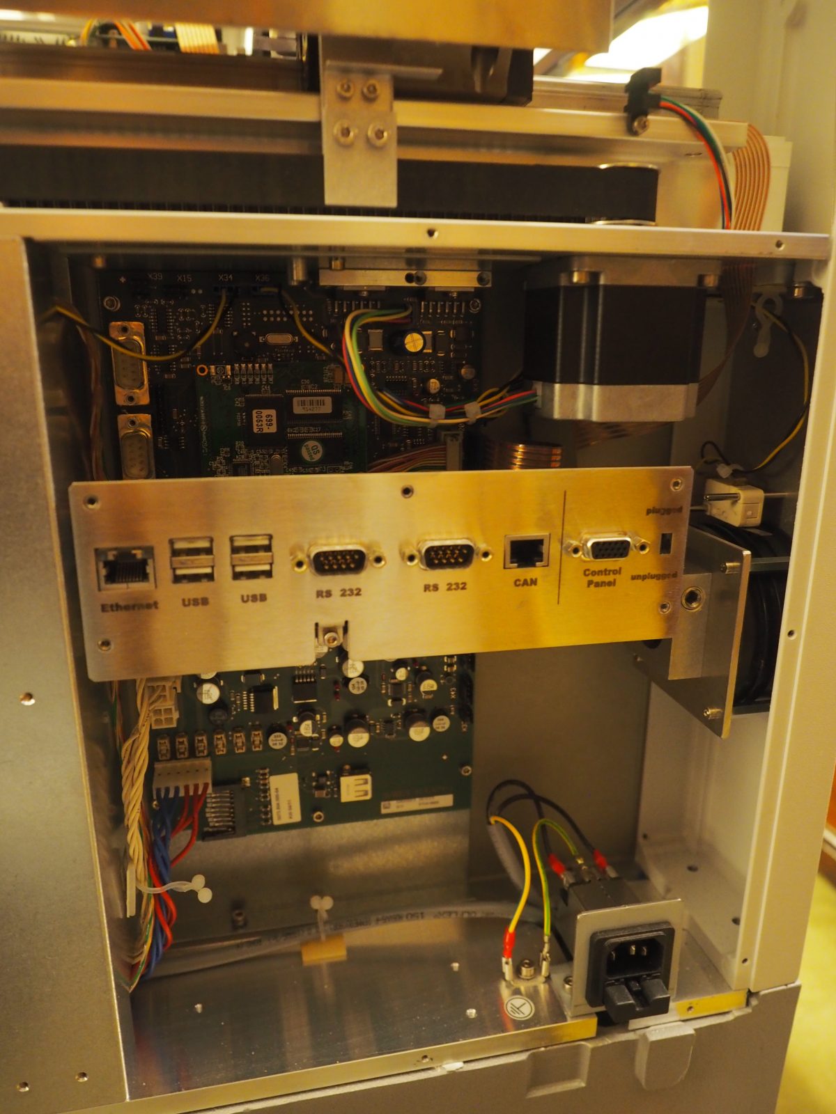
The back panels come off very easily with a hex-key and expose the computer that runs the machine. This runs some version of Windows, maybe Windows CE. It has USB and ethernet ports although to my knowledge with my version of this robot these can’t be used for anything useful. In general I doubt there is any easy way to make this computer do anything other than what Eppendorf has programmed it to do, without access to the underlying source code.
Removing the top required in my case removing a little bit of double sided tape at either side, in addition to two hex-key bolts.
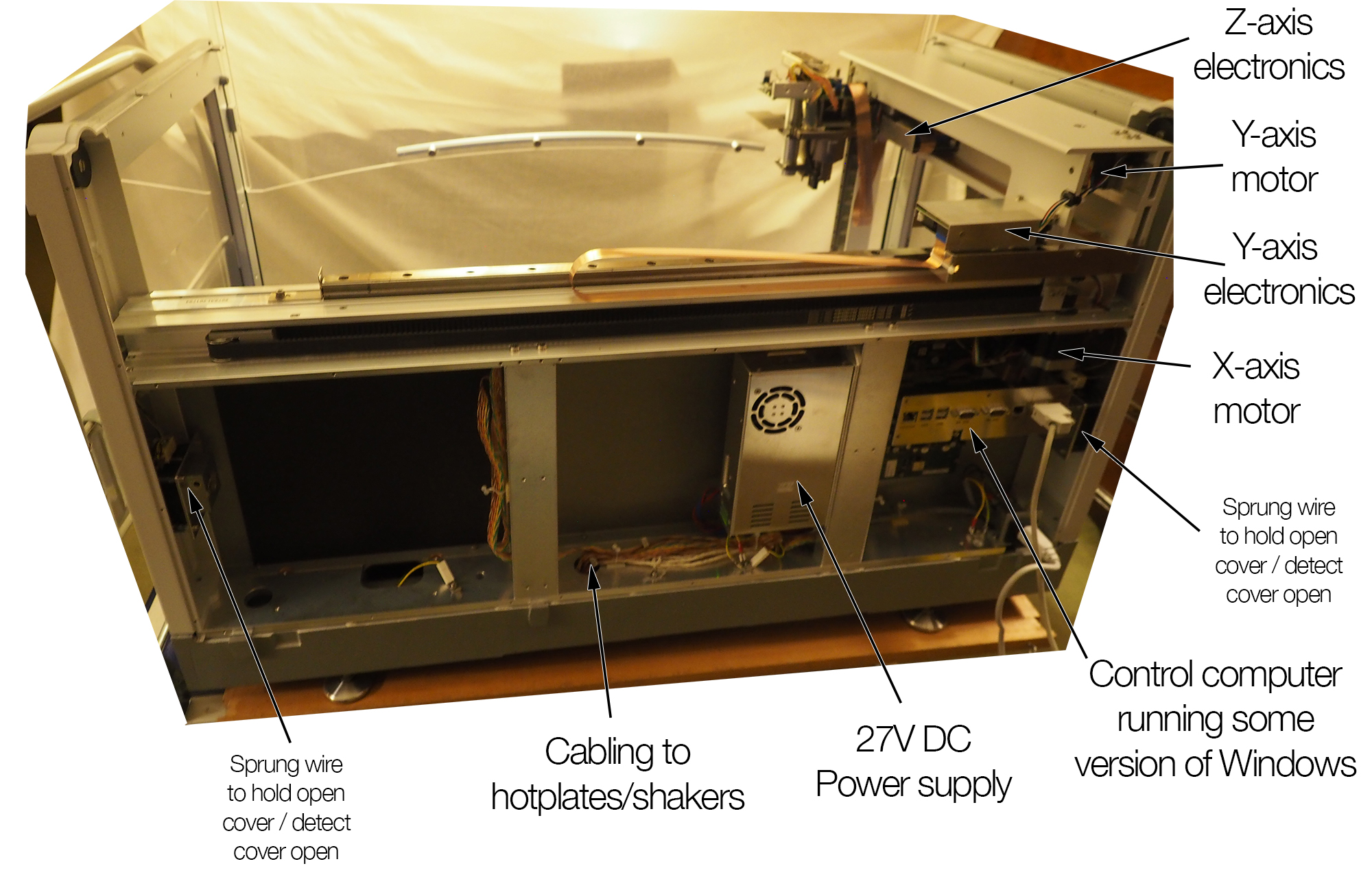
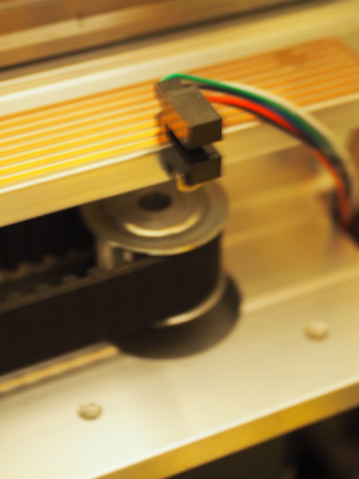
There is a heavy-duty belt for the X axis with a big stepper motor. My robot had been essentially unused for several years and the rail over which the X-carriage runs had become covered with a sticky substance. This caused the motors to stall mid-run, but cleaning them off with some alcohol resolved this issue.
Basics
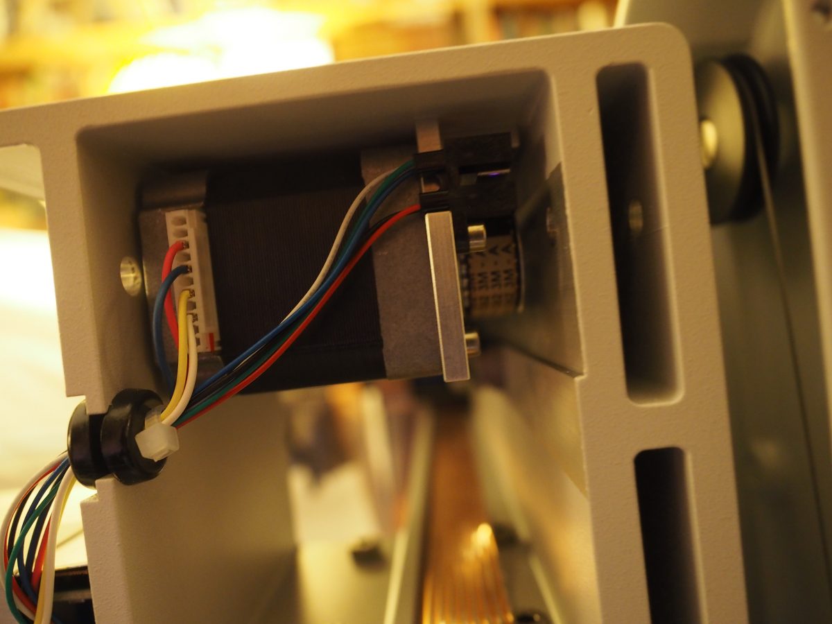
Each of the X, Y and Z axes is controlled by a stepper motor (the X-axis one is this). They each have optical endstops with 4 wires. In the video above these endstops have been replaced with mechanical switches but it really should be possible to use them as-is.
Cabling
One of the challenges of making a many-axis robot is that signals have to be carried to each successive axis, all of which are connected together. So flexible cabling is needed -but at the same time it has to not get in the way or fall into the samples. In the case of the epMotion this is carried out with ribbon cables like this:
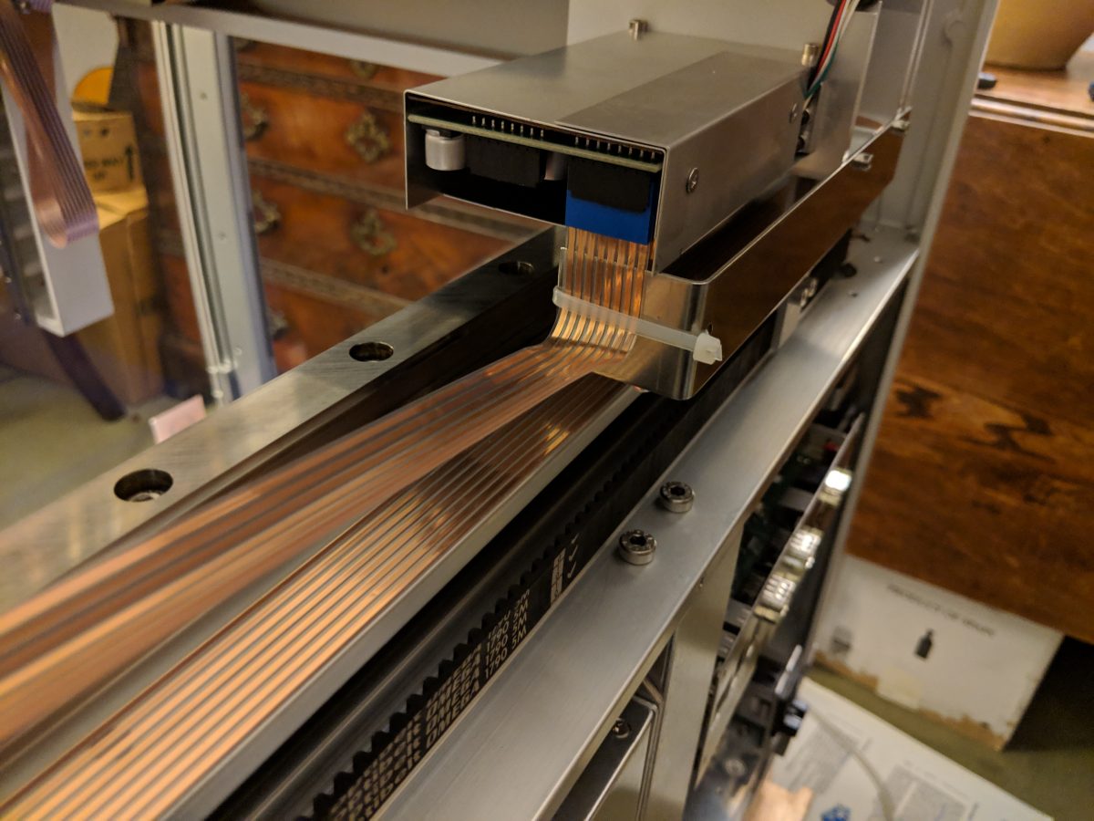
But it quickly becomes apparent that this cable doesn’t have enough wires to be simply directly connected at the other end to stepper motors / endstops / etc. Instead it seems that this is some sort of serial cable that carries data signals to a series of other microprocessors, one on the robot’s pipetting arm, and one for each of the Y and Z axes, which then interface with the Y motor, Z motor, the tool locking motor, the pipetting motor, the tip-ejecting actuator, and the range-detector.
If you want to hack this thing you’ll have to decide whether you want to have to make and mount 4 separate pieces of control hardware, or to replace the cabling with a much thicker set of wires.
Pipetting arm
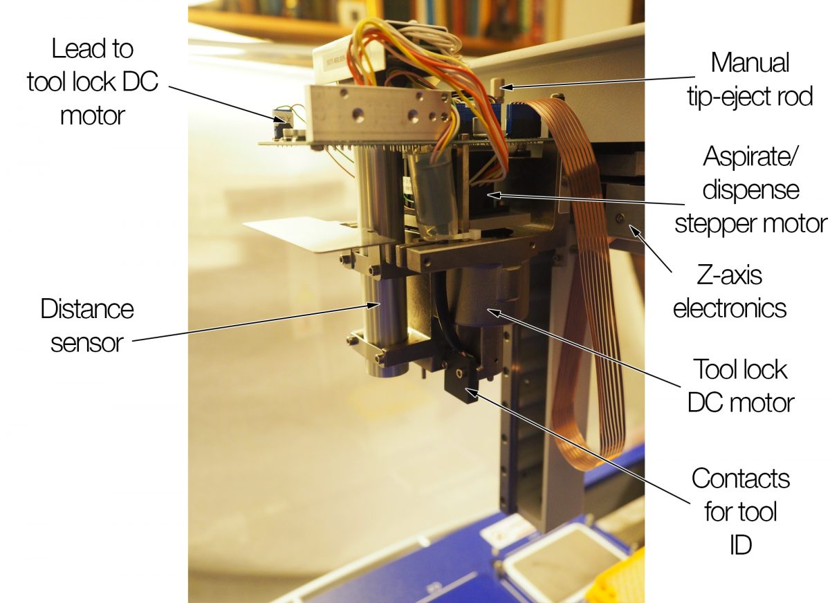
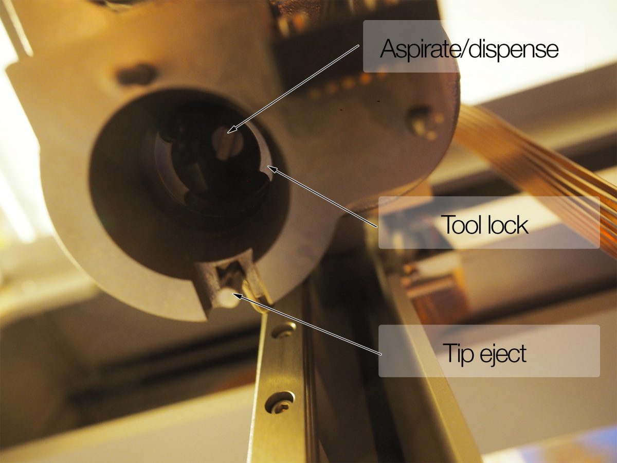
Lurking under the metal cover of the tool arm is a profusion of electronics. There’s a lot to do. An (infrared?) sensor to measure distance, and actuation of grabbing a tool, identifying it, pipetting up and down, and ejecting a tip.
Selecting/using tools
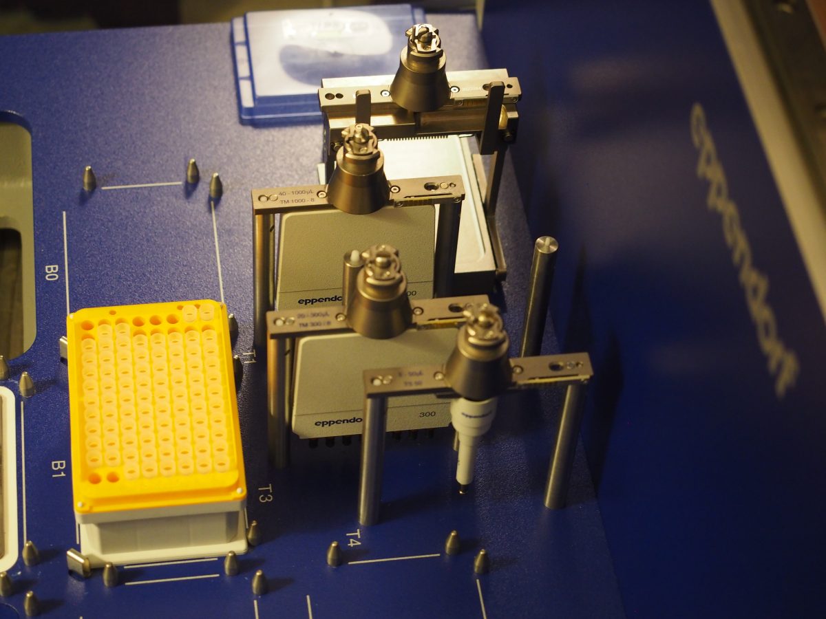
One of the very impressive things about the epMotion robot is its ability to change tools during operation. It can choose from a variety of single channel and multichannel pipettes, and even a plate gripper.
How does this process work?
The tool arm has two coaxial motors. One is, I believe, a simple DC motor with a very low gearing. It rotates a bit of metal internal to the arm which causes it to firmly grip whichever tool it is currently over. I’m not quite sure how the robot knows when this rotation is finished. My suspicion is that it detects the change in current flowing through the motor when the motor stalls at the end. Certainly if you disconnect this motor, the robot is able to detect that ‘the engine is not responding’, and informs you so.
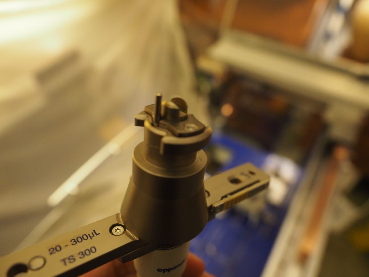
When one examines the pipettes themselves one notices they have electrical contacts, but these are simply used to tell the robot which tool is in what place. The pipettes are in fact mechanical rather than electronic devices. They all have the same rotatable top-piece, and as this is spun by a stepper motor in the tool arm they aspirate/dispense liquid (or in the case of the gripper, grab and release). As this piece is rotated the tool begins to extend a rod out from it. Inside the tool-gripper this rod must make contact with a switch, and this is used to “home” the pipette to ensure the robot knows the position of the plunger.
Prospects for customisation
I’m going to pause my hardware work here, because it isn’t yet clear exactly what the application of the robot will be for me and I don’t want to destroy any necessary functionality.
If I had continued I would have one way or another tried to marry up the epMotion hardware with the open-source OpenTrons robot-control software. This basically means adapting the hardware such that one knows how to control it and then writing a custom driver for the OpenTrons software.
I do think this is completely achievable. The video above already shows how 3-axis control is possible, using a standard CNC board. Controlling aspirate/dispense as a fourth axis should be similarly simple. If my understanding of how the tool interlock works is correct than that also wouldn’t be too challenging – one would just need to measure the current flowing through the motor. An even simpler strategy would just be to keep one tool locked onto the machine.
One decision one would have to make would be whether to have a single control board and have lots and lots of wires running to the tool-arm, or to use the existing ribbon cables and have a separate controller on the tool arm controlled over serial. I suspect the latter might be the better approach.
More generally, if I do this I will have to consider whether I want to be limited to expensive epMotion robot tips, the only ones compatible with any of these tools. I suspect the answer is no. In that case I might end up bolting an OT-2 electronic pipette to the pipetting arm, though this again loses the advantages of tool-changing. Or maybe I’ll go with something completely different like a vacuum pump and a peristaltic pump – we’ll see.
In general none of this looks trivial, and one is almost certainly better off just buying an inexpensive OT2. Still, it’s nice to have a better understanding of what is going on inside this intricately engineered machine.
Update:
It has just occurred to me (another useful reason for writing things down) that there may be an easier and less invasive way to get control of this thing. If one can reverse engineer the serial control that the computer uses to control the Y-axis, Z-axis, tool interlock, aspiration tip ejection (and distance measuring) then one can get control of all of these without messing with their hardware. It seems possible that this could be achieved relatively simply (if they are sent in a text-based format) and when I have access to the machine again in 6 months time I will investigate. The 8 leads in the ribbon cable could be: V+, GND, Y-out, Y-in, Z-out, Z-in, pipette-out, pipette-in.
Theo Sanderson
Assistant Professor
Biologist developing tools to scale pathogen genetics.