Saving 99.5%: automating a manual microscope with a 3D printed adapter
**TL;DR: **Some 3D-printing hackery can create an automated microscope stage from a manual stage for ~0.5% of the cost from the manufacturer.

I have always wanted access to a microscope with an automated stage. The ability to scan an entire slide/plate for a cell of interest seems to unlock a wealth of new possibilities.
Sadly, these systems cost quite a bit. The lab I work in now has a Leica DMi8 microscope with automated movement in Z. But XY movement is (on our model) still manual. It is possible to purchase an automated XY stage for this microscope, but the list-price quote is around £12,000 (including stage, and control hardware and software).
I’m not going to argue that this price is unreasonable. I am sure that the manufacturers of scientific equipment spend a lot of time and money innovating, and that money has to be made back by selling devices which have relatively small production runs. Nevertheless, the result is that the costs of kit that makes it to market are fairly staggering – and this prevents someone like me from being able to play around with an automated stage.
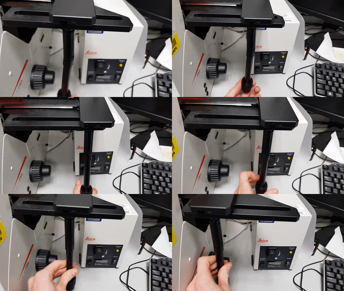
But I still wanted to experiment with an automated stage! So I wondered how easy this would be to do myself. After all, we have a manual stage, and we move it by rotating two knobs. Couldn’t I just get motors to turn those instead of doing it with my hand?
As I thought this through further I realised it was slightly complicated than this. Firstly, the knobs are co-axial, making them rather harder to deal with than would be two separate shafts. And secondly, as you rotate the X-knob, the shaft moves in X.

So the motors need to be able to move with it. But they also need to be to rotate and exert a twisting force on the knob – so they need to move linearly but be locked in one orientation.
Hardware: 3D printed pieces, 2 stepper motors and a RAMPS controller
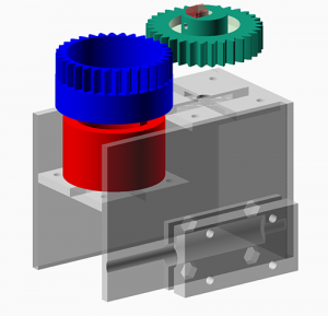
I made a quick design in OpenSCAD

Basically the first knob,which controls movement in Y, is simply connected to the mechanism by a (red) sleeve which connects to a motor below. The knob above, which controls movement in X, is placed inside a (blue) sleeve which covers it in a gear. That gear is turned by a (turquoise) gear turned by a second motor. Both motors are mounted on a (transparent) piece which also connects them to a LM6LUU linear bearing which allows them to slide but keeps their orientation constant.
I printed out these 3 pieces – then tweaked the dimensions a little to be more snug on the knobs and printed them again. The final STL files, and the SCAD file that generated them are available on Thingiverse.
To control it I connected the steppers to a trusty RAMPS 3D printer controller. These cost £30 with a screen and a rocker controller (the Leica hardware to control a stage is ~£3k). Since the 3D printer controller is also all set up to control the temperature of a hot-end and a heated bed, if you want to add warm stage down the line this might be ideal.
Initial tests controlling the position using the system using the RAMPS controller went well, and let me calibrate the number of steps per micrometer.
Software: MicroManager
Regrettably, the Leica software isn’t going to allow you to easily hook it up to an Arduino-based controller. But, as ever, open-source software comes to the rescue. Micro-Manager is a very advanced ImageJ plugin that can connect to the Leica camera, and to the microscope itself to control filter cube positions, Z-focusing, etc.
Don’t expect quite the user-friendliness of Leica software from Micro-Manager, but _do _expect a wealth of packages to perform common operations in automated-microscopy (Leica charges ~£2.5k for the software to revisit a position multiple times – which was included in the quote given above).
Theoretically, MicroManager even allows you to control XY position using a RAMPS controller – someone has already written a package for exactly this board. This step, which should have been trivial, was actually the most complicated. The device adapter is designed to ask the RAMPS controller for its version, and somehow I could never make my board submit a response that the software was happy with. I had to download the MicroManager source and remove the code that checked the version. Successfully setting up the build environment for Windows took an age. Do get in touch if you have a similar project and want the DLL I built [update: DLL here, I offer no guarantees at all that it will work. This is an x64 build which will only work with a recent nightly build] [update 2: Nikita Vladimirov has followed up on this and released the changes he had to make to MicroManager]. Anyway, to cut a long story short I got MicroManager to talk to the RAMPS board successfully.
Testing by making a 100X oil immersion slide scanner
Now to put it into practice.
I wrote a Beanshell script to scan a slide in X and Y and capture images. In this case I captured images in a grid 40 microscope images wide by 30 microscope images high, for a total of 1200 images.
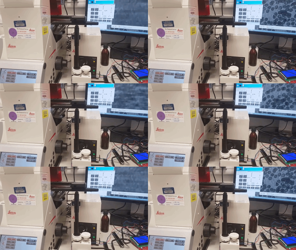
This took a few minutes – try doing that by hand.. Then I stitched them together with the MIST plugin. The result is a 27,000 x 12,000 pixel image, featuring a whole lot of red blood cells. You can zoom in on the version below. This was taken with a 100X oil immersion objective, at which magnification the smallest motion of the stage is a substantial fraction of the image, but still allows enough overlap for stitching.

Fun! Still a bit more experimenting to do, but I’m hoping to get this acquiring tagged proteins from 96-well plates.
Caveat for anyone who tries to implement this: obviously be very careful not to create significant non-twisting forces on the coaxial knobs – you don’t want to damage your stage and ruin the alignment.